
Third Party Controllers
This section outlines any third party controllers that can be used parallel to CORE and VCM Live. The list below outlines all available controllers:
| ■ | TurboLamik TCM |
TurboLamik Setup Procedures
The below step-based procedure outlines how to setup a TurboLamik TCU (Transmission Control Unit) with HP Tuners CORE ECU (Engine Control Unit) using VCM Live in two different procedures (CAN Configuration Setup and VCM Live Setup). If you are looking for instructions on how to install a TurboLamik TCU, please refer to the TurboLamik Manual.
CAN Configuration Setup Procedure
| 1. | Download the latest VCM Live Beta (download here). |
| 2. | Open VCM Live. |
| 3. | Click the |
NOTE: CORE communicates via CAN so setting up requires connecting the TurboLamik to one of the designated CAN ports, with the matching bitrate on the TurboLamik side.
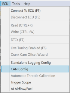
| 4. | In the menu bar click ECU > CAN Config . |
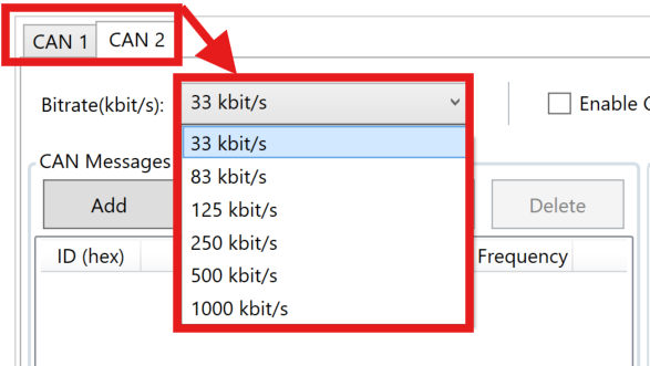
| 5. | In the CAN Config window select the CAN port that is physically connected to the TurboLamik TCU (CAN 1 or CAN 2) and ensure the bitrate matches the bitrate on the TurboLamik TCU. |
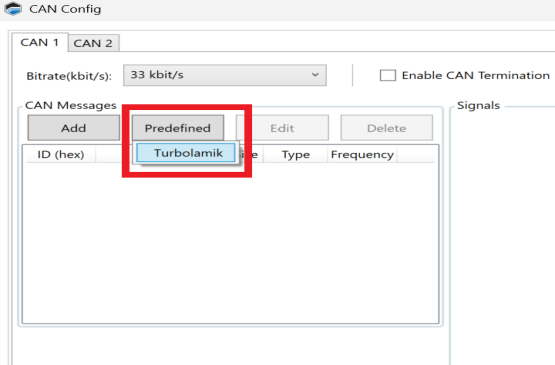
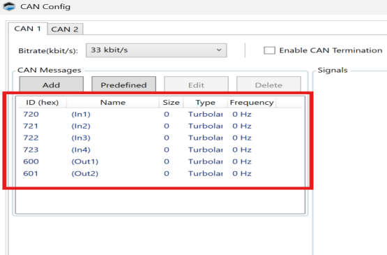
| 6. | Click Predefined > Turbolamik. |
CAUTION: These are grouped messages, if one gets deleted the entire group of messages will be deleted.
| 7. | Click Ok. |
| 8. | Click |
NOTE: Ensure "CAN Config (Ready):" Write check box is checked off (refer to image below).
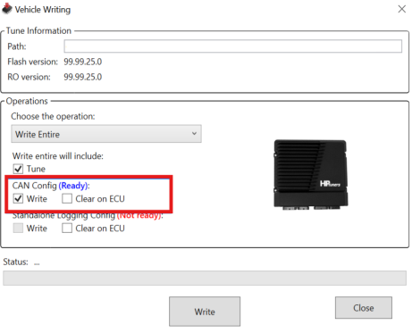
| 9. | Click Write. |
| 10. | TurboLamik Can Configuration is now complete, refer toTurboLamik VCM Live Setup Procedure to setup all TurboLamik associated Parameters. |
TurboLamik VCM Live Setup Procedure
| 1. | Open VCM Live (if not already opened). |
| 2. | In the menu bar click Layout > Import Layout > From Additional > TurboLamik. |
| 3. | Click Tune > Open Tune and select the latest Tune file. |
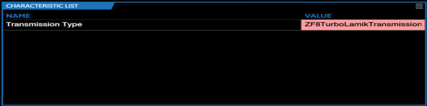
| 4. | Ensure to change the characteristic Transmission Type parameter to the ZF8TurboLamikTransmission value. |
| 5. | Enable Blip Control , by selecting the below values for all of the below characteristics. |
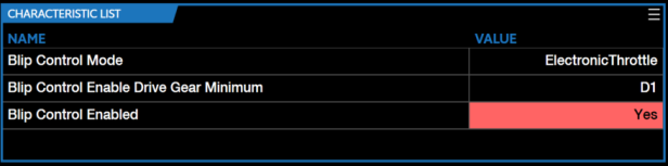
NOTE: CORE Blip Control allows users to set a defined throttle position during transmission downshifts. This feature is exclusively applicable to the ZF8 transmission.
| 6. | Activate all of the below characteristics with the below values. |
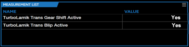
NOTE: "TurboLamik Trans Target Gear" - "TurboLamik Trans Current Gear" indicates downshifting.
NOTE: Blip Control is activated when all of the above conditions are met.
| 7. | Tune blip behavior with the below characteristics. |
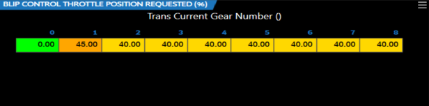
| a. | "BLIP CONTROL THROTTLE POSITION REQUESTED (%) |
NOTE: This table defines the throttle position during a blip.
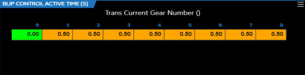
| b. | "BLIP CONTROL ACTIVE TIME (S)" |
NOTE: This table defines how long the blip is maintained. Once a downshift blip is triggered, no additional blip will be allowed until the defined duration has elapsed.
| 8. | Utilize the "TURBO-LAMIK TRANSMISSION IGNITION RETARD (°)" characteristic to retard the ignition angle (spark) to enable smooth transmission shifts |
NOTE: TurboLamik provides the torque reduction (%) to CORE, which then uses this input to retard the ignition timing based on the below table.
![]()
| 9. | TurboLamik is now ready to be utilized. |
